Experimental Fluid
Dynamics Laboratory
Research

The Experimental Fluid Dynamics Research Lab conducts experimental fluid dynamic and aeroacoustic investigations in their hybrid anechoic wind tunnel, anechoic chamber and recirculating water tunnel facilities using state-of-the-art instrumentation, including laser-based flow diagnostic tools (such as planar- and stereo-PIV, and V3V), hot wire anemometry, linear- and phased- microphone array systems, hydrogen bubble and die visualization systems, and steady and unsteady pressure transducers.
Aircraft landing gears and wing slats are the two most significant sources of airframe noise during the approach and landing phases of modern commercial aircraft. As the noise sources are closer to the ground and the duration of the noise heard from the ground is longer due to reduced airplane speeds, airframe noise becomes critical to communities living near airports during these phases of flight. In addition, curved or straight cylindrical cavities located on the outer body of aircraft and multiple antennas in various arrangements can lead to tonal noise generation. With the worldwide expansion of air transportation, aviation noise has become one of the most disruptive by-products of aircraft. As a result, aviation-governing authorities around the globe have been acting on this issue by imposing a series of increasingly stringent noise limits on aircraft. These regulations phase out the noisy aircraft designs from commercial routes and impose landing fees on airlines based on their aircraft's noise emissions. Consequently, airlines are inclined to purchase quieter aircraft in the market, which creates massive competition among aircraft manufacturers. Partnering with Bombardier, our research team works to contribute to the development of quieter aircraft. To this end, we execute systematic aerodynamic and aeroacoustic investigations to advance insight into the underlying causes of noise from these primary airframe noise sources, and using this understanding, we attempt to develop radical noise reduction strategies. For further details, please read the specific projects on landing gear, wing slat, cavity and antenna noise on our website.
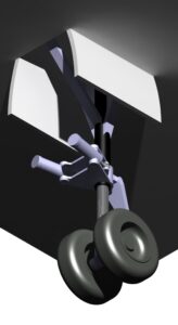 This project is conducted in partnership with Bombardier. Aircraft landing gears are one of the major noise sources. The broadband noise produced by lading gears is governed primarily by the turbulence characteristics and the local mean velocity of the flow. Current generation landing gears have very complex architectures, consisting of a large number of small- and large-scale components, such as torque links, lights, steering actuators, drag stays, main fittings, tow hooks, dressings, hydraulic lines, bay cavities, bay doors etc. The local turbulence characteristics and mean flow velocities that each of these landing gear components is exposed to differ significantly due to the occurrence of complex flow interactions between them. Moreover, the noise radiation directivity also varies for each component due to their dissimilar shape and orientation. As a result, the generated broadband noise is very complex, spanning a wide frequency range, including the frequencies to which human hearing is most sensitive. Redesigning the shape and/or position of a landing gear component can change the local flow conditions for adjacent landing gear components, thereby altering their noise contribution. This makes developing noise reduction concepts for landing gears a remarkably challenging problem. It is not uncommon to see low-noise concepts derived from a purely heuristic intuition leading to noisier designs. Development of effective noise reduction strategies requires a thorough understanding of the flow dynamics, underlying noise generation mechanisms and how these are affected by the design variations. At present, these issues are not fully resolved, and the aerospace community is currently in active pursuit of this knowledge. Today's landing gears are mainly designed to support the safe landing of aircraft with lesser attention to their acoustic performance. Our research team at the Experimental Fluid Dynamics Research lab works to improve insight into the noise generation mechanisms of landing gears and develop physics-inspired component modifications and flow control concepts for landing gear noise mitigation.
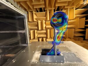
This beamforming map shows noise sources in red contours at a particular frequency of interest. Data obtained through EFDL's phased-array microphone array is processed through the delay and sum beamforming algorithm.
This project is conducted in collaboration with Bombardier. Wing slats are devices used during the take-off and landing of an aircraft to enhance its lift performance at low speeds. They are one of the primary airframe noise sources. The unsteady slat flow and its relation to noise generation have still not been fully explained. This is because the slat flow in the cove involves rich, unsteady fluid dynamics (including flow separation, flow recirculation, and free shear layer) and has common features with several canonical problems, such as splitter plate mixing layers, cavity flows, and flow past backward-facing steps, with variations arising due to the proximity of the slat trailing edge, shape of the cove and flow acceleration in the gap between the slat and the wing. Most past experimental studies aiming to determine slat flow and noise information have mostly been conducted on unswept models, missing the added spanwise flow present in swept systems. However, in reality, most airplanes have swept wings. Only a few experimental studies exist on swept high-lift models, and as a common weakness, in all those studies, the acoustic tests were done in open-jet anechoic wind tunnels, which restricted these studies to small angles of attack due to strong susceptibility to flow deflections in open-jet tunnels. At present, there is a lack of knowledge regarding the effects of the sweep angle on the flow dynamics in the slat cove, slat noise and slat noise generation mechanisms. Hence, our team is characterizing the aerodynamic and aeroacoustic features of swept three-element (slat-wing-flap) configurations, employing our PIV, unsteady and steady pressure measurement and phased microphone array systems in our newly commissioned hybrid anechoic wind tunnel. This tunnel can go from open-jet or hard-walled wind tunnel configurations to a Kevlar-walled tunnel. The advantage of Kevlar walls is that they contain the test-section flow for high angles of attack while permitting sound waves to the surrounding anechoic chamber, where far-field noise can be measured.
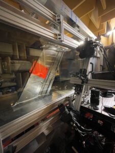
Figure shows the swept three-element (30P30N) model in the anechoic wind tunnel with the stereo-PIV arrangement.
Also, nearly all past studies did not include any slat accessories (e.g. tracks and actuators), joints or wing cut-outs, although these details are under crossflow effects in swept systems. These accessories on real aircraft are designed mainly for operational purposes with minimum consideration of their impact on noise. In this program, we are evaluating the impacts of these slat accessories on the flow and noise generation for both swept and unswept configurations, and using this understanding, we are working to develop modifications on the slat accessories to reduce aircraft slat noise.
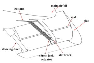
Sketch shows typical accessories, joint and cutouts in a slat cove region.
This project is conducted in partnership with Bombardier. High-amplitude tonal noise generation can result from airflow over the mouths of cylindrical cavities located on the outer body of aircraft. Typically, exhaust ducts of various aircraft systems, such as the engine cowling anti-icing systems, fuel overpressure vents, water drain vents and wastewater systems, have cylindrical cavities associated with them. The tonal noise contribution from a resonating airframe cavity can easily be 10 to 20 dB above the overall airframe broadband noise, increasing the certification noise levels for aircraft. Moreover, cavity tones are generally observed to occur in the frequency range for which human hearing is most sensitive. Therefore, they can cause significant annoyance and disruption to those living close to airports or along flight corridors. Several cavity tone suppression concepts can be implemented to reduce the cavity noise; however, they often lead to significant modifications in the pressure field at the cavity mouth. For many aircraft systems, this side effect is acceptable. However, for cavities that require passing specific airflow rates through them, significant changes to the exhaust duct pressure can adversely impact the operation of the system. For example, for cavities associated with the engine cowling anti-icing system, a reduction in the pressure field at the exit of the anti-icing duct as a result of a tone suppression measure may increase the exhaust speed of the heated de-icing air, having a detrimental impact on the operation of this critical safety system. Whether or not cavity resonances are excited depends on the geometry of the cavity and the local flow conditions (e.g., crosswind). Accordingly, it is extremely difficult to predict the potential of cavity tone generation during the aircraft design stage, where the sizing requirements for the exhaust ducts are determined for critical systems, and often, the generation of tones is only discovered much later during flight testing. Problems of this sort can delay the timelines associated with aircraft certification, requiring expensive rework of the design under tight time constraints.
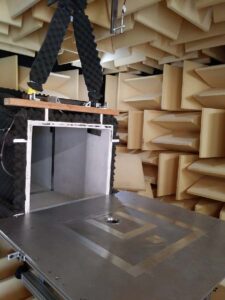
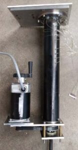
Presently, little knowledge exists regarding the impact of commonly accepted tone suppression devices on the mouth pressure field of cylindrical cavities. As indicated above, this information is important for systems, such as the engine cowling anti-icing ducts, where the mass flow rate through the exhaust system is critical for the system's operation, and hence any method devised to suppress tones in such systems should not reduce the pressure at the exit of the duct more than acceptable levels. Furthermore, the engine cowling anti-icing system as well as some designs of wastewater systems consist of curved cylindrical ducts. It is currently unknown if the tone suppression concepts commonly used for straight cavities are also applicable to cavities with more complicated curved shapes, how the curved shape of a cavity impacts the suppression concepts, or if a better solution can be devised for curved configurations. Our study at the Experimental Fluid Dynamics Research lab aims to address these shortcomings in knowledge by evaluating various tone suppression concepts for both curved and straight cylindrical cavities and their impact on the pressure at the mouth and within the cavity.
 |
 |
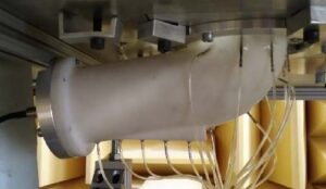 |
| Cavity test setup in the anechoic wind tunnel | Straight cavity setup with pressure ports | Curved cavity setup with pressure ports |
We collaborate with Bombardier on this project. Antennas on the airframe may contribute to tonal noise because of the regular shedding of vortices. Modern aircraft are equipped with several antennas to fulfill various operational functions. Although flow interference between circular cylinders in tandem, side-by-side or staggered configurations has been studied intensively, investigations related to the noise radiating from rods in such arrangements have remained limited. A previous experimental study carried out by NASA on a number of cylinder configurations, including tandem and side-by-side, found that arranging two smooth cylinders in tandem with small spacing results in about 6 dB noise reduction compared to the noise level emitted from them on their own (as a single cylinder). On the contrary, they also showed that at larger separation distances, the level of the aeolian tone from tandem cylinders increases 2-4 dB higher than that of the single cylinder. However, this conclusion was totally reversed when the upstream cylinder was tripped by a collar distribution, which shows the complexity of the interference effects on radiated noise. Mechanisms leading to such variations in emitted noise for different arrangements of cylinders have never been investigated. An immediate question that comes into mind is: why do smooth tandem cylinders placed in close proximity radiate lesser noise than the single cylinder? A full physical understanding of the mechanisms leading to such large variations in noise levels for various arrangements of cylindrical structures is essential for the aircraft industry to consciously determine the best distribution for their antennas for the removal of tones. Therefore, we aim to build knowledge grounds in this realm by deciphering the correlations between the acoustic response and flow dynamics associated with different model configurations. Since many components of landing gear (struts, cables, axles, wheels) can also be modelled as rods of various lengths and cross-sections, such detailed characterization of the wake interference effects on the radiated noise is also relevant to our landing-gear noise reduction efforts.
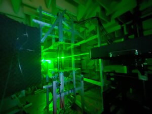
Figure: PIV measurements on tandem body arrangements in the anechoic wind tunnel.
Flow-induced vibration in most engineering applications must be suppressed to prevent structural damage. In contrast, methodologies may also be needed to amplify structural vibrations to harness electricity from hydrokinetic energy sources. Adopting specific surface protrusion devices can provide a practical control strategy. However, the knowledge to design such control means is still incomplete. We explore various protrusion devices for both suppression and increase of vibrations. The former would benefit engineering structures suffering from vibrations, while the latter would provide a green energy alternative.
| Movie: Amplification of vortex-induced vibrations of a bluff structure using a tripwire at a critical location. | Movie: Suppression of vortex-induced vibrations of the same bluff structure using the same tripwire at another critical location. |
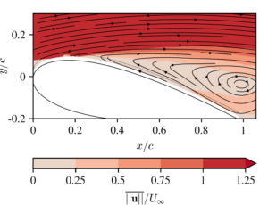
Delaying or eliminating flow separation from critical aircraft surfaces can reduce drag, decreasing fuel burn (and, thereby, harmful gas emissions). Such separation control can also diminish separation noise (an effect prevalent in various locations in aircraft) and suppress interruptions to lift generation. It would be ideal to have a technology that effectively reduces or eliminates flow separation and does this with small parasitic drag, little energy consumption, and a simple design. One such technology, which has shown promising results for flow control in laboratory tests, is synthetic jet actuators. Their compact design and no need for external mass addition make this technology attractive for aeronautical applications. However, a major issue associated with this technology is that the actuator itself is loud during operation. Although their flow control performance has been studied widely, the current knowledge lacks low-noise synthetic jet actuator designs suitable for aeronautical use. Our team investigates methods for reducing synthetic jet actuator noise while achieving the desired flow control performance for aviation applications. Such technological advancement would promote the use of synthetic jet actuators as a green aviation technology. This project was initiated through the highly competitive Dean’s Strategic Fund.
 |
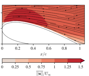 |
| Flow separation in the uncontrolled flow past NACA 0.025 at 12 deg angle of attack. (Time-averaged streamlines overlaid by the contours of velocity magnitude.) | Delay in flow separation for the synthetic jet actuator controlled flow past NACA 0.025 at 12 deg angle of attack. (Time-averaged streamlines overlaid by the contours of velocity magnitude.) |
 |
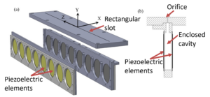 |
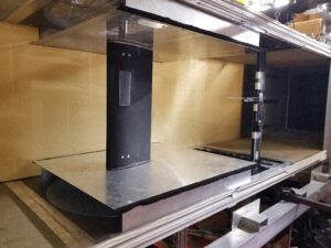
| The NACA 0.025 fitted with the synthetic jet actuator array in the wind tunnel. | Inside look of a synthetic jet actuator array. Exploded view of the array. |
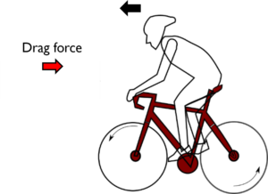 Little is known about the impacts of the pedaling characteristics of an athlete on the drag and flow in cycling. Although the motion of the moving limb of an athlete is more complex, much can be learned from studying the flow characteristics in the canonical case of a yaw oscillating cylinder, which represents the dominant motion experienced by an athlete’s limb. To explore the effects of an athlete’s limb motion on cycling aerodynamics, in collaboration with Prof. Hanson from York University, we study the influence of the yaw oscillation motion of a circular cylinder at various frequencies on the near wake as a reduced-order model.
Click the movie to see the wake structure behind a yaw oscillating cylinder at reduced frequencies of K=1 on the left and K = 1.3 on the right. Results obtained through PIV measurements.
When a boundary layer encounters an obstacle protruding from the surface, it separates due to the adverse pressure gradient and rolls up to form three-dimensional complex vortices, known as horseshoe vortices. In the case of wing-body junctions, horseshoe vortices can raise skin friction (and thus, drag), degrade the wing lift characteristics, and generate unwanted vibration, dynamic stress and noise. The drag induced by the wing-fuselage junction is estimated to be 10% of the total drag in modern civil airplanes. Another situation, where horseshoe vortices have dramatic effects, is a turbine blade-hub junction. In this case, horseshoe vortices can affect increase the local heat transfer rates and thereby cause thermal gradients in the blade. To reduce such adverse effects, we develop passive flow control methodologies that are easy to implement at the wing-body junction.
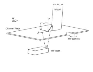
The figure shows the sketch of the experimental system where PIV measurements are conducted to assess a short triangular leading-edge plate at the base of a wing-body junction as a passive control method to eliminate the horseshoe vortices or at least to subdue their strength.
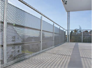 Perforated panels are often used for their aesthetic appearance on the exterior façades of buildings. These perforations are usually circular; however, different geometries of perforations may also be employed. One major problem associated with such architectural elements is their tendency to produce loud noises when exposed to winds. While this noise is generally broadband in nature, for certain wind speeds and directions, some perforation dimensions produce strong tonal noise, described as howling and humming. Tonal noise is often found to be more irritant than broadband noise. Some famous examples where undesirable tonal noise generation from such panels were seen include One World Trade Center in New York City, USA, Beetham Tower in Manchester, UK and 8 Eglinton Avenue East in Toronto, Canada. The adverse impacts of architectural panels on the noise environment of communities is unacceptable. During the construction phase of buildings, architects and designers often overlook the possible noise problem for perforated panels, and the realization of this problem afterwards requires costly replacements of the panels with a different product (which is the only known solution at this point). In recent years, the widespread use of these panels by building architects has made the associated tonal noise problem a prevalent environmental concern. In the Experimental Fluid Dynamics Research lab, we explore the tonal noise generation problem by such perforated panels (consisting of circular holes) as well as slotted plates (consisting of long rectangular bars) as their two-dimensional counterparts and assess the viability of various geometric variations as noise mitigation measures. This project was initiated through a collaboration with Aercoustics Engineering Ltd.
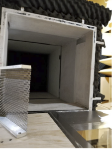
Figure shows the setup of the perforate panels in our anechoic wind tunnel.
Understanding flow past a group of cylindrical bodies is of great significance for many fields of engineering design. Interference between the bluff bodies can, in certain cases, result in a highly complex flow physics. Practical scenarios where these flows occur include: landing gear components, heat exchanger tubes, adjacent tall buildings, and piles of offshore platforms in a stream of fluid, to name a few. The cylinders, in these applications, can be in a group of two, three, or more.
Investigation of the fluid dynamics of simple body configurations helps us understand the flow around more complex structures, such as landing gear components or the flow past neighbouring buildings. In this project, two cylinders in tandem and side-by-side arrangements are considered. Particularly, we investigate the evolution of the wake flow behind stationary cylinders over a range of spacing as well as cylinders that are subjected to forced crossflow vibration over a range of spacing, frequency, amplitude, and phase angle between the oscillating cylinders.
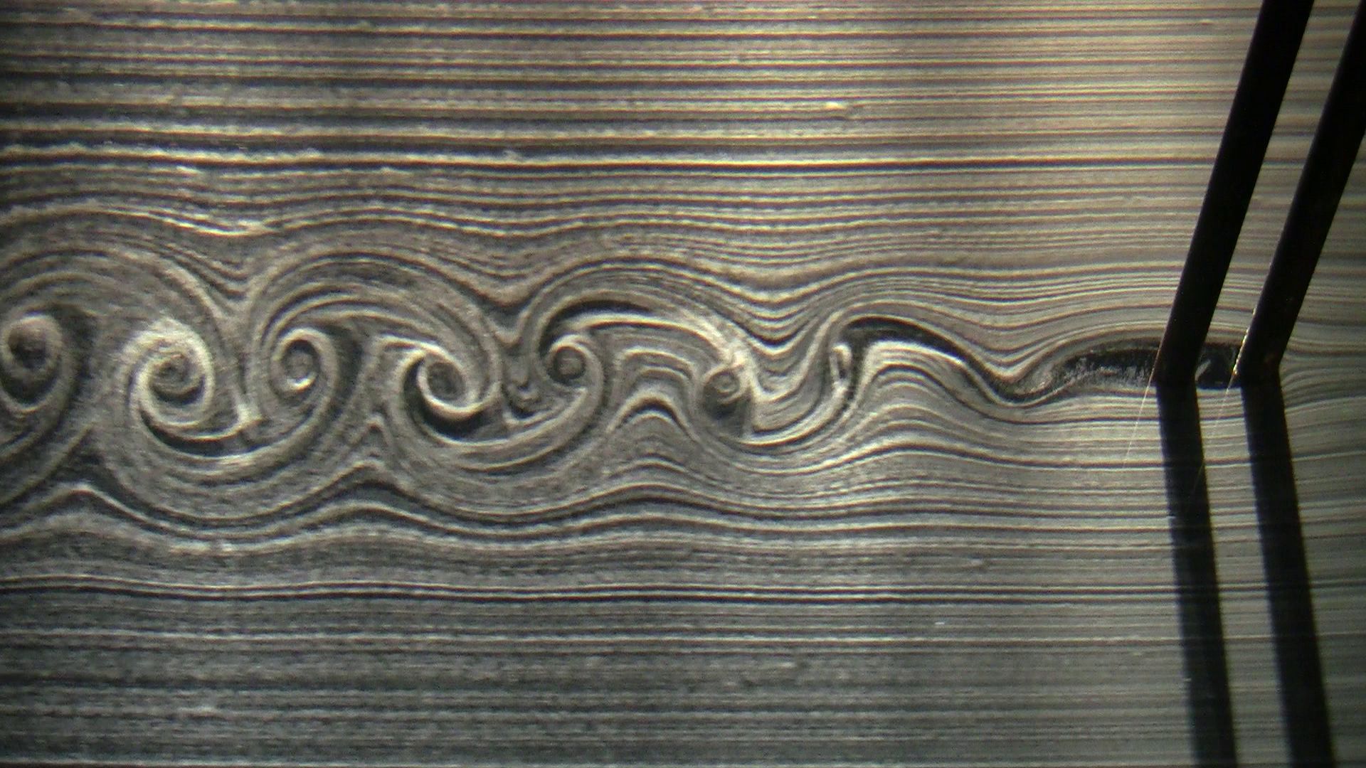
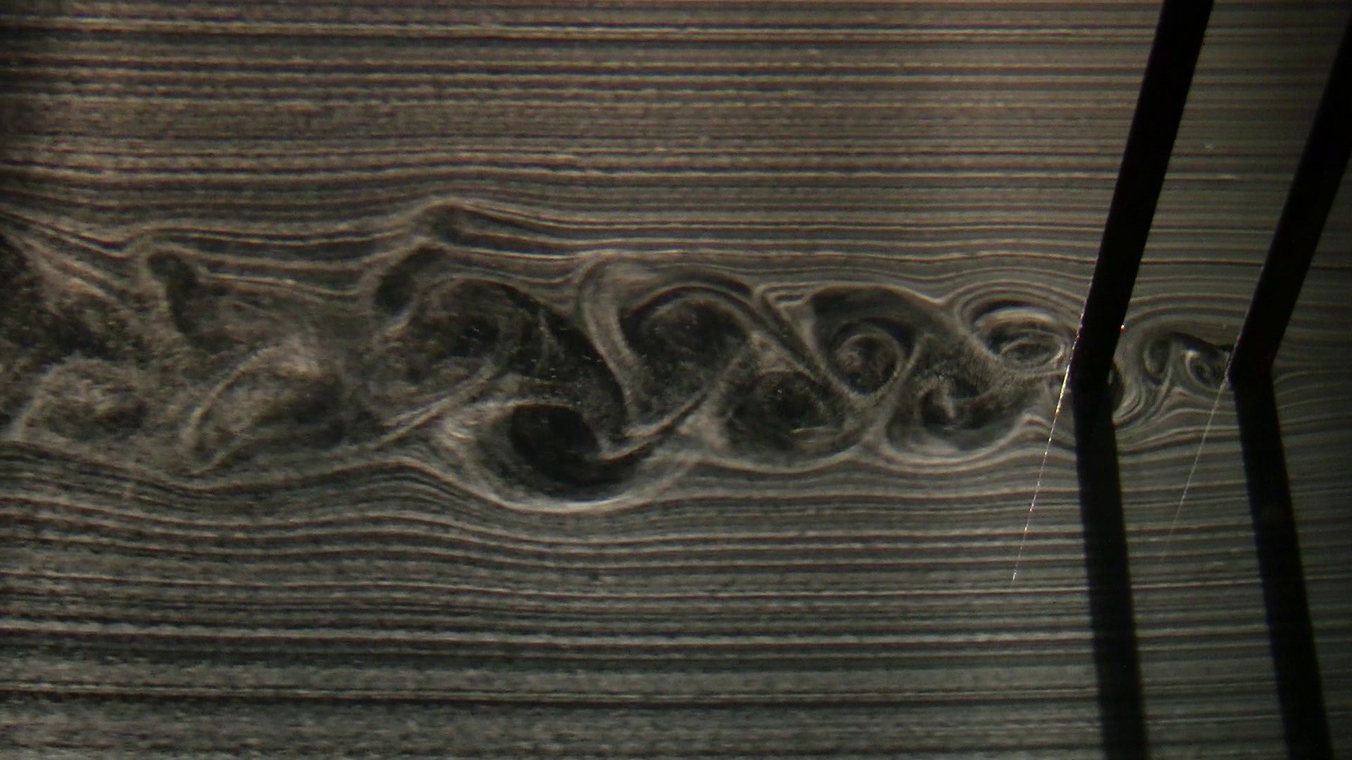
A representative result obtained via hydrogen bubble visualization technique. The wake structure behind two stationary cylinders in a tandem arrangement is visualized here. Cylinders are two cylinder diameters apart on the left image and four cylinder diameters apart on the right image. The flow direction is from right to left.
This project is initiated through a collaboration with Multimatic. The performance, handling, safety, and comfort of automobiles are affected by their aerodynamic properties. Traditional tools used by industry to evaluate the aerodynamic performance of automobiles are wind tunnel experiments and road tests. Full-scale experimental testing is expensive and time consuming. The use of scaled models, while less expensive, is subject to flow similarity discrepancies. To meet consumer demand and stay competitive, automotive companies must develop new techniques to avoid the high economic costs and long development times of experimental tests. Computational Fluid Dynamic (CFD) tools have emerged to fill this requirement, as they offer a cost-effective alternative to design optimization. CFD analysis of automobile flow fields is challenging. The external geometry of automobiles is extremely complex, the flow field is fully three-dimensional and turbulent, and flow separation is common. In order to validate the CFD software, simulation results must be compared with experimental measurements during the development phase. The research performed at the Experimental Fluid Dynamics lab focuses on high-quality experimental measurements of canonical automobile models to produce an understanding of the unsteady flow field around automobiles, a topic that is still not understood. In addition, we work to provide a comprehensive database of experimental data for which validation of the accuracy/robustness of CFD for automobile simulations can be performed.
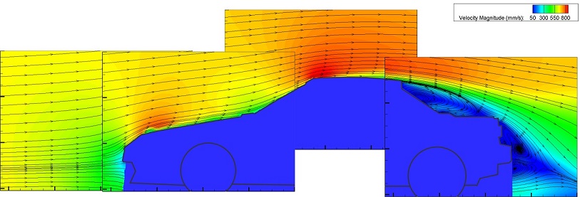 |
| Figure shows a representative PIV result we obtained on a model car. Time-averaged streamline topology is superimposed over velocity magnitude contours. |
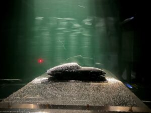 |
| Figure shows hydrogen bubble visualization setup for a car model. |
Flow-Induced Cavity Resonance and Its Control
Flow over cavity-backed openings can give rise to flow oscillations that are strongly coupled with the acoustic or free-surface resonant-mode of the cavity. Such strong oscillations can lead to vibration in the structural components of the cavity and associated noise generation. Flow-induced cavity resonance is encountered in a variety of systems, such as in the cavities located on the fuselage of an aircraft, the hull of marine vessel, and the ballast tank of a submarine, to name a few.
This project investigates the means of controlling cavity resonance. So far, flow control through a slotted plate arrangement plaecd at the mouth of the cavity is tested for various open area ratios and plate geometries. A cinema technique of high-image-density PIV is used to characterize the spectral amplitudes and phase variations on either side of the slotted plate. This experimental study provided the first detailed characterization of the flow associated with the fully-coupled oscillations of shear flow past a resonator cavity in presence of a free surface. As an important benchmark, the work developed novel criteria for slotted plate design to suppress flow-driven instabilities and vibrations in cavities. For further details on the project, interested fellows can check the following two journal publications:
- Oscillation of shallow flow past a cavity: Resonant coupling with a gravity wave
- Self-sustained oscillations of shear flow past a slotted plate coupled with cavity resonance
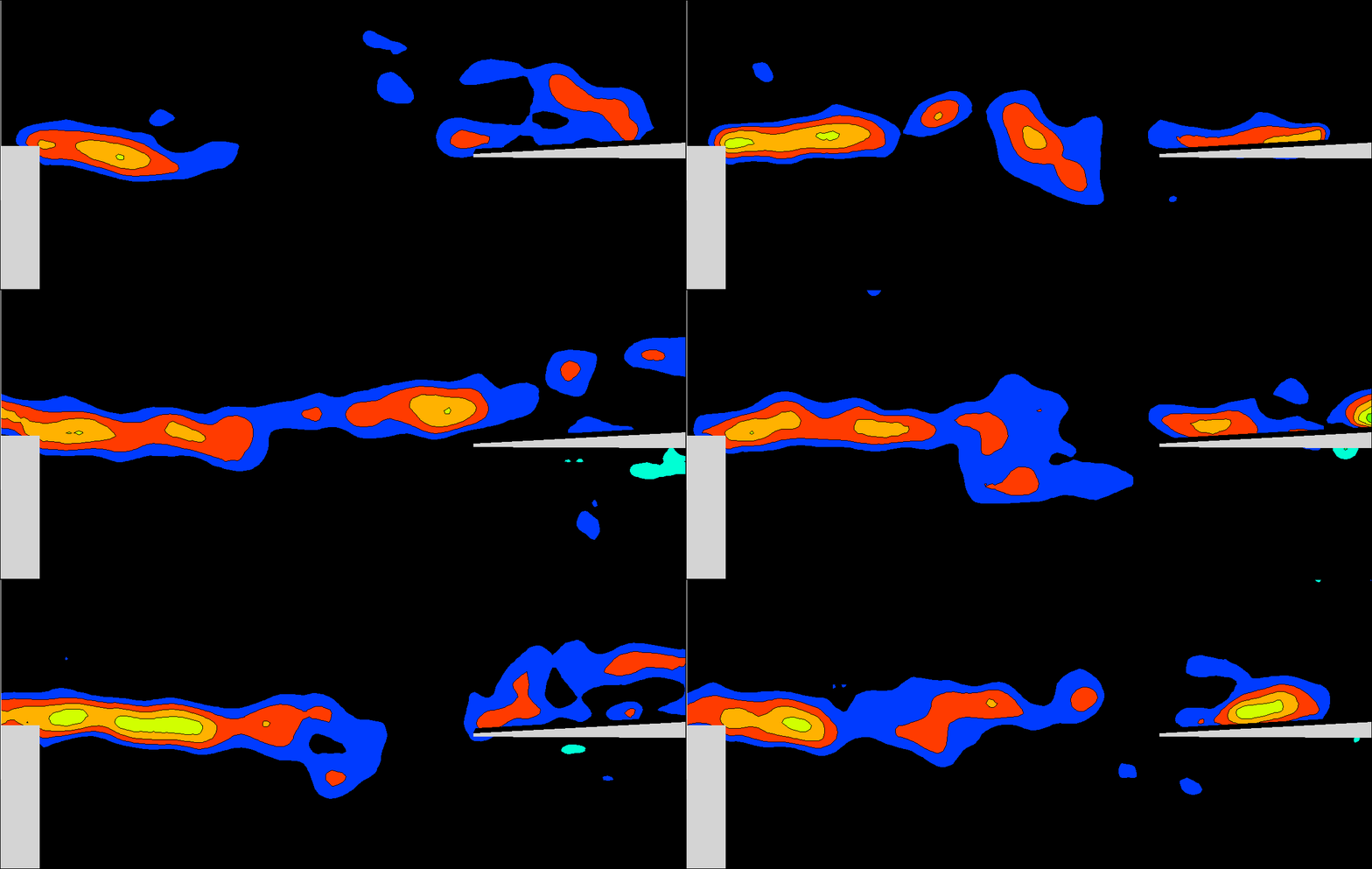
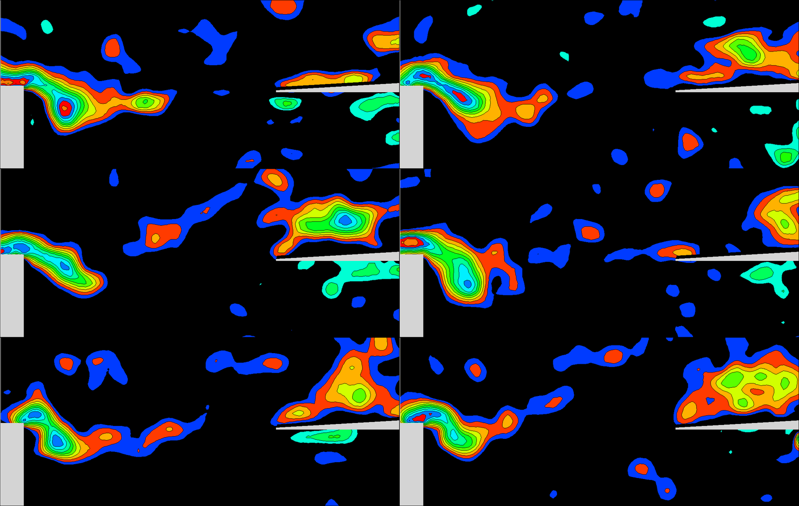
Movie: The movies above compare the vorticity contours of the shear layer past the cavity openning at non-resonant state at the top and at the resonant state at the bottom. The separating shear layer is horizontal at the non-resonant state. It, however, deflects from the horizontal and forms a large-scale vortical structure at the resonant state. The large-scale vortices periodically impinges onto the end of the cavity, which is a potential for flow-induced vibration of the structure and noise.
Non-Coupled State Marginally-Coupled State Fully-Coupled State

Figure 1: Instantaneus vorticity contours for non-resonant, marginally-resonant and fully-resonant states are given respectively in the first to third columns of images. Flow direction is from left to right. In the top row, patterns of free shear layer past the cavity are provided. For this case, the shear layer forms a large vortical structure as the fully-coupled state is approached. In the bottom row of images, a slotted plate is placed at the cavity openning. In comparison to the structure of the free-shear layer, the spatial extent of large-scale vorticity clusters are reduced in presence of the slotted plate.
Non-Coupled State Marginally-Coupled State Fully-Coupled State

Figure 2: Fluctuating flow structure: The patterns above show the root-mean-square value of the transverse velocity fluctuations normalized with respect to the free-stream velocity for non-resonant, marginally-resonant and fully-resonant states directly corresponding to the images given in Figure 1. In the top row, patterns of free-shear layer past the cavity clearly show the substabtial increase of the peak fluctuation magnitude with increasing degree of coupling. On the other hand, in presence of the slotted plate, given in the second row of images, the peak magnitude of velocity fluctuations are relatively attenuated. Flow control through different geometries of slotted plate arrangements is further investigated in our studies. For further details, please see the journal paper, link to which is provided above.Flow over cavity-backed openings can give rise to flow oscillations that are strongly coupled with the acoustic or free-surface resonant-mode of the cavity. Such strong oscillations can lead to vibration in the structural components of the cavity and associated noise generation. Flow-induced cavity resonance is encountered in a variety of systems, such as in the cavities located on the fuselage of an aircraft, the hull of marine vessel, and the ballast tank of a submarine, to name a few.
This project investigates the means of controlling cavity resonance. So far, flow control through a slotted plate arrangement placed at the mouth of the cavity is tested for various open area ratios and plate geometries. A cinema technique of high-image-density PIV is used to characterize the spectral amplitudes and phase variations on either side of the slotted plate. This experimental study provided the first detailed characterization of the flow associated with the fully-coupled oscillations of shear flow past a resonator cavity in presence of a free surface. As an important benchmark, the work developed novel criteria for slotted plate design to suppress flow-driven instabilities and vibrations in cavities. For further details on the project, interested fellows can check the following two journal publications:
- Oscillation of shallow flow past a cavity: Resonant coupling with a gravity wave
- Self-sustained oscillations of shear flow past a slotted plate coupled with cavity resonance


Movie: The movies above compare the vorticity contours of the shear layer past the cavity openning at non-resonant state at the top and at the resonant state at the bottom. The separating shear layer is horizontal at the non-resonant state. It, however, deflects from the horizontal and forms a large-scale vortical structure at the resonant state. The large-scale vortices periodically impinges onto the end of the cavity, which is a potential for flow-induced vibration of the structure and noise.
Non-Coupled State Marginally-Coupled State Fully-Coupled State

Figure 1: Instantaneus vorticity contours for non-resonant, marginally-resonant and fully-resonant states are given respectively in the first to third columns of images. Flow direction is from left to right. In the top row, patterns of free shear layer past the cavity are provided. For this case, the shear layer forms a large vortical structure as the fully-coupled state is approached. In the bottom row of images, a slotted plate is placed at the cavity openning. In comparison to the structure of the free-shear layer, the spatial extent of large-scale vorticity clusters are reduced in presence of the slotted plate.
Non-Coupled State Marginally-Coupled State Fully-Coupled State

Figure 2: Fluctuating flow structure: The patterns above show the root-mean-square value of the transverse velocity fluctuations normalized with respect to the free-stream velocity for non-resonant, marginally-resonant and fully-resonant states directly corresponding to the images given in Figure 1. In the top row, patterns of free-shear layer past the cavity clearly show the substabtial increase of the peak fluctuation magnitude with increasing degree of coupling. On the other hand, in presence of the slotted plate, given in the second row of images, the peak magnitude of velocity fluctuations are relatively attenuated. Flow control through different geometries of slotted plate arrangements is further investigated in our studies. For further details, please see the journal paper, link to which is provided above.
Aerodynamic Evaluation Of The University Of Toronto Solar Car
To remain competitive, team competing in the World Solar Challenge must constantly improve the aerodynamics of their vehicle designs. In collaboration with the University of Toronto Blue Sky Solar Racing team, the 2013 B-7 Solar car was tested to evaluate areas for aerodynamic improvement. Analysis using PIV has shown drag-producing separation from the driver canopy, which will be addressed in the next design iteration

