Front Cockpit Workstation
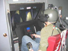
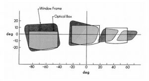
Images are projected into 3 seperate windows by 24in Sony Multiscan colour (CRT) monitors. Each monitor projects through a VITAL II infinity optics window box. The resolution in each window is 1280×1024 pixels. The nominal field of view for each monitor is 40° x 30° resulting in a pixel resolution of approximately 2 arcminutes. See the figure below for the as displayed field of view.The forces are generated by electric DC servo motors coupled to a two stage, low inertia, zero backlash speed reducer which in turn is linked via a push pull rod to a force transducer and the flight controls linkage. The autothrottles are moved through a backdrive feature to their desired deflections. The system is operated by a digital computer which is coupled to the simulator’s flight computer via a fiber optic cable and a reflective memory interface. The manufacturer specifies a force loop frequency response of greater than 100Hz.
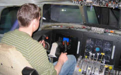
The 4000X control loaders can produce a continuous force output of ±412 lb and much larger peak values. Their stroke is ±2 in. The control column has a travel range of 5.5 in (14cm) forward and 9.3 in (24 cm) aft. The control wheel has a travel range of ±120°. The pedals have a travel range of ±2.6 in (6.6 cm). The 2000RC control loaders can produce a continuous torque output of ±XXX ft.lb with a continuous rotational capability.
Rear Cockpit Workstation
The cyclic stick control forces are provided by a McFadden Systems Inc. Model 292B Universal Variable Digital Cockpit Control Force Loading System. The stick forces are generated by rotary servo actuators of the limited rotation vane type with hydrostatic bearings. An electro-hydraulic servo valve controls each of the two actuators using analog electrical signals fro the digital unit’s digital-to-analog converter. Differential pressure and angular position transducers are used to provide feedback for the force and modeling loops. A digital control loop closes the force generation process with a 5 kHz update rate. The manufacturer specifies a 80 Hz bandwidth for this loop. The mathematical model that generates force commands to the system in response to stick displacement also runs at 5 kHz. This model can have its parameters updated in real-time at up to 1 kHz.
The system can generate a maximum force of ±150 lb at the stick’s hand grip on both axes. The maximum pitch displacement is ±15.3° (±7.37 in) and the maximum roll displacement is ±15.5° (±7.47 in). The force resolution is better than 0.1 lb at the hand grip.
Main Simulator Components
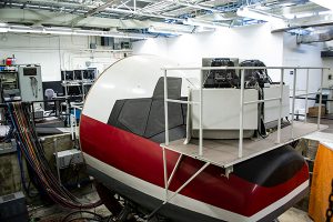
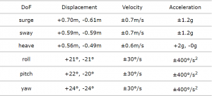
The CAE 300 Series Hydraulic Motion Base is a six degree-of-freedom Stewart platform. The six actuators have a stroke of 91.4cm, a bore of 8.9 cm and are equipped with hydrostatic bearings. Power for the system is provided by 3 37.3kW squirrel cage induction motors with matching variable displacement in-line pumps. The measured motion characteristics of the system are:
Bandwidth of 10Hz (3dB point)
Bandwidth of 5Hz (90° phase-nominal, can be extended)
Dynamic threshold < 67ms
Hysteresis < 1mm per actuator
The motion envelope (1 Dof at a time is),
- simENGINE™ graphics cards with ATI graphics processors
- Fill rate 12 Gpix/sec peak
- Anti-aliasing 2 to 24 samples
- Polygons 186M tri/sec peak
- Channel syncronization
- Trilinear mipmap texture anti-aliasing
- Up to 2048×2048 texture map
- 256MB memory
- Texture compression
- LOD (24 levels)
- 32 bit true color
- Gamma correction
